When you click on links to various merchants on this site and make a purchase, this can result in this site earning a commission. Affiliate programs and affiliations include, but are not limited to, the eBay Partner Network.
I looked over the V-AFC wiring diagram, the Vortech wiring diagram, and the plug and play harness very carefully. It seems to me that if the Vortech wiring is wired directly into the OEM wiring (NOT the plug and play harness), then the plug and play harness will be perfectly configured for adding the V-AFC into the loop without problems. The V-AFC would be controlling the MAP voltage AFTER the Vortech MAP controller had already done its "thing".
I took the VAFC harness out today to study for the wirings.
Doooh one of the wires on the harness felled out
It doesn't matter too much becoz
I think I found the solutions and will need an electrician to do some more soldering for me anyway.
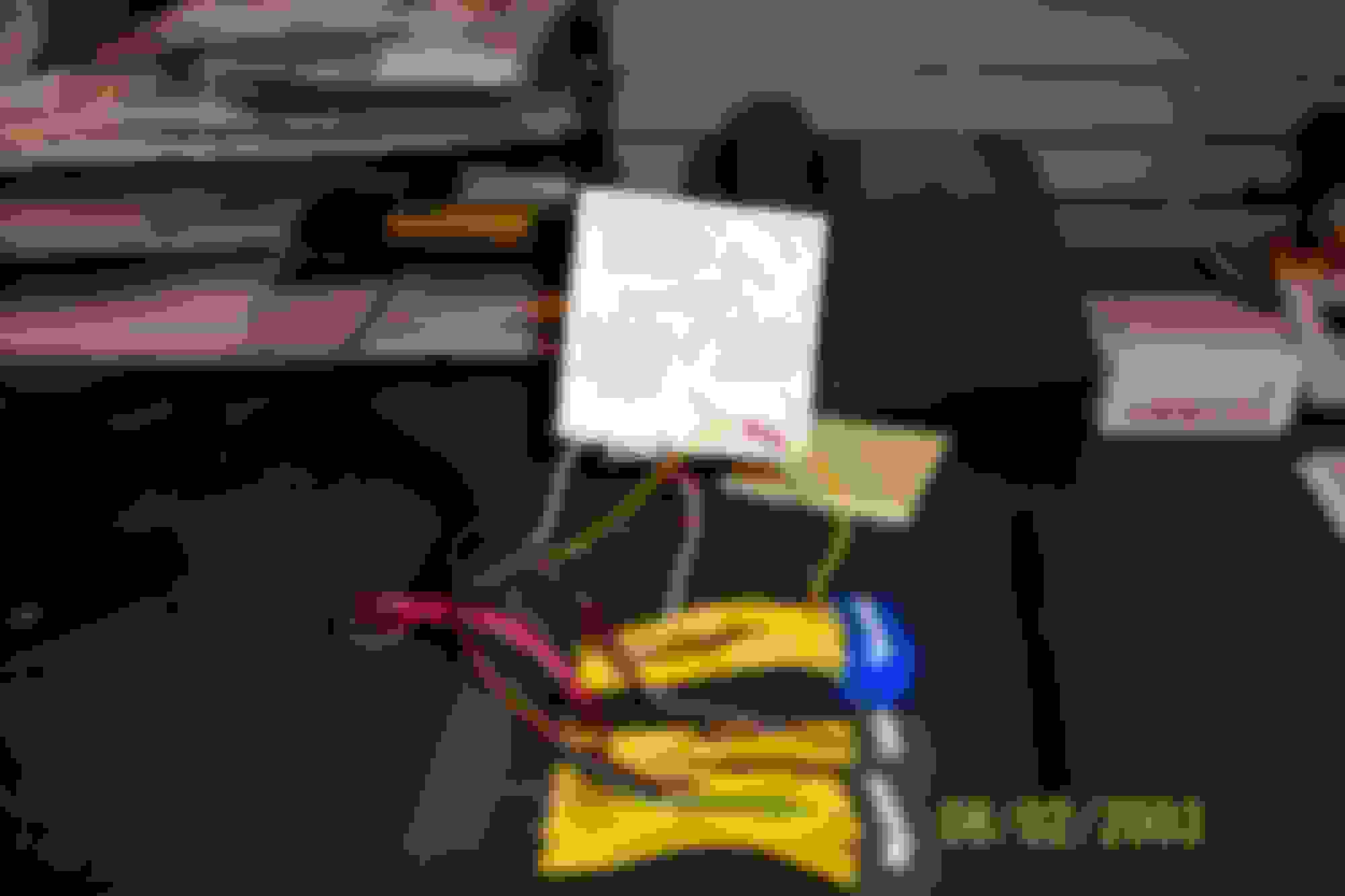
Looking at the pics above and page 32 of Vortech manual.
Blue and white from the MAP controller should be tapped to the white wire on the VAFC harness.
Summary
1. Signal should flow from MAP>>Vortech Black boxes>>VAFC and then ECU
2. Harness photo: hook the Vortech black boxes to the left side of the harness only ie before the VAFC
3. Blue and white from the MAP controller should be tapped to the white wire on the VAFC harness. So it goes like this MAP sensor (white line)>>Blue wire>> MAP controller>>White wires>>VAFC>>Yellow line>>ECU
We will find out after the weekend.
I've sent my harness to some one to solder on the wires. I am not a believer in crimp/clamp (??spelling) connections.
just cut/splice/tap the oem wiring harness just like the vortech manual says to do. The harness will plug N play just as it is designed.
if you do decided to splice the harness you will still have to splice the oem harness MAP 17 wire, this will still have to be done the way the vortech manual says. Reason? to keep the vafc from seeing boost, if the vafc see's boost then the ECU will also. The map controller needs to be spliced in on the oem harness, so that boost pressure is blocked before hitting the vafc via the harness.
I hope this helps. I just got back from running my car for an hour and no CEL and NO boost was seen by the VAFC or ECU.
All I did was plug the vafc + harness back in the way it was designed to begin with!

 08-04-2003, 10:52 AM