When you click on links to various merchants on this site and make a purchase, this can result in this site earning a commission. Affiliate programs and affiliations include, but are not limited to, the eBay Partner Network.
The positive illumination wire (red/black) runs on both sides of the dash. Some of the pictures in the posts above were taken from a right-hand drive (RHD) model. Assuming that your car is a left-hand drive (LHD) version, the pictures will not match your car. When I did the installation on my LHD MY08, I also found that some of the LHD pictures included in the above posts did not match my car. I believe that the location of the connectors/grounds moved throughout the model years (seems plausible as the electrical system was updated throughout the life of the car). For me, I found that I could tap into the red/black wire using a connector next to my fuse box. But, like the instructions given in post #2, I decided to use the unused illumination connector in the fuse box and avoid the tap entirely. At any rate, it is very likely that you will need to extend the red/black wire that is included in the Footwell kit (just like is mentioned in post #2). The sure way is to obtain the electrical troubleshooting guide for your model year, and use it to locate the best possible location to access the illumination wire (again, my opinion would be the fuse box). Hope this helps. Good luck.
Rather than tapping into the factory wiring for the illumination circuit, simply utilize the un-used illumination spade on the fuse box, or add it in to your wiring if you're already using it for gauges etc. Simply extend the short red/black wire on the footwell LED kit harness to reach all the way to the driver's side of the car. You'll need several feet of 20AWG wire. At this stage you can go as crazy as you want to extend this wire. Use a butt connector, or solder & heat wrap, un-tape the harness so you can run the wire within the corrugated loom in conjunction with the other wires & re-tape, or just leave it separate from everything. The sky is the limit on how cleanly you want to extend this wire.
To terminate the wire you can either use a bare spade terminal, or get fancy and crimp on the appropriate connector, a 1 pin Sumitomo HD 250, which you can buy from SOS or other sources. Here's two separate sources, you do you.
Feeling foolish here but I can't figure out these clips. I ordered the 1-pin connectors from Cycleterminals and it came with brass connectors. But they don't seem to fit into the brown plastic clip. Does the white part of the brown connector lock the brass disconnect into place somehow?
How else do you connect wire to the brown clip? There doesn't seem to be any metal inside so I have to assume I'm missing something.
You do not have to tap into factory wiring if you don't want to. (There are some great connectors that are easy to use however)
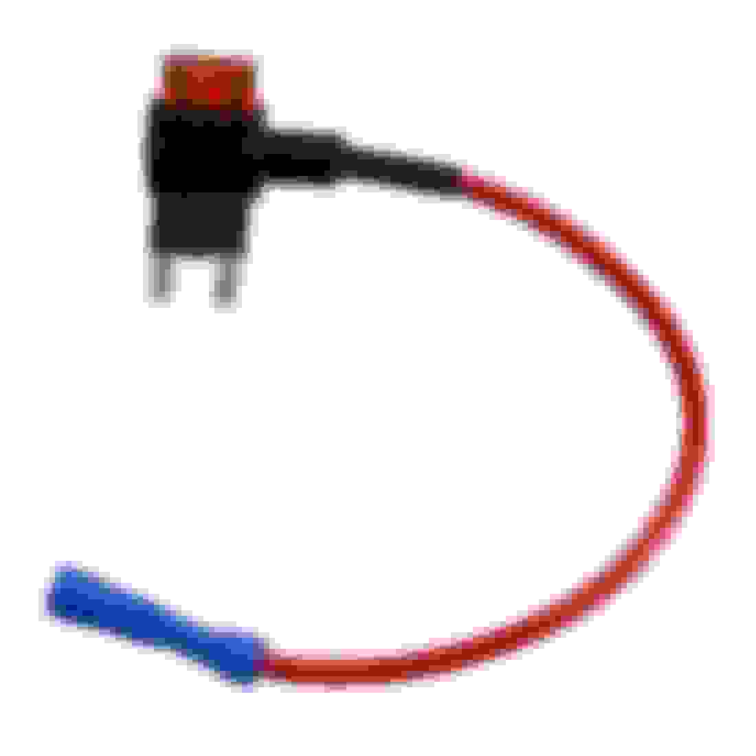
You can "add a circuit" and therefore have a dedicated fused circuit to your lights. I did that and used the fuse that supplies the 12v plug on the console. There is an inline fuse that goes to the LED footwell lights. Very easy. Except of course, lying on your back under the dash to wrap things up!
Thank you @kyle and everyone else that contributed to this tread. Got mine installed this evening and everything went as noted in the post. Had ordered the correct clip and wired directly to the fuse panel. Adds just the right amount of light and enjoyed the opportunity to tinker with the S.
After doing this myself this weekend, I would add a couple of small details:
All 4 of my black self-tapping screws were the same, no shorter pointy one.
My kit came with a nice grounding bolt, which I didn’t use. Save it. It may come in handy for something else down the road. While you’re saving things, save all documentation, such as it is. These cars are becoming collectors items.
The mounting bracket for the driver side light fits BEHIND BOTH metal tabs, *not* sandwiched between them. See pic.
In my ‘08, and I assume all AP2s, the ground screw is in a slightly different location from the AP1 pictures and is practically inaccessible. Yes, you can take out the module and bracket that are in the way, but who really wants to do that when you’re upside down and working inside such a small cavity. I cut off the ring terminal on the ground, soldered an extension and ran the ground to another location. I also considered cutting a notch out of the ring, turning it into a fork, so I could slide the ground underneath the bolt, but again, too difficult a space to work in. Plus, the ground wire was so short that access to the in line fuses for the lights would’ve been blocked if I’d used it as is.
Buy some Sumitomo HD250 female connectors online (~$2.50@ if you search around. Science of Speed marks them up 4x unfortunately), use the proper crimp tool, and connect into the driver’s side under dash fuse box into the unused illumination slot (unless of course you have something else you’ve added there). Yes, you have to extend the illumination wire, but that’s easy and is a much cleaner install without tapping into anything. If you’re really ocd, you can do yourself and future owners a favor and label that wire. I labeled it “footwell” and clear heat shrunk the printer label onto the wire.
Hey guys! Seems to be a bit of confusion surrounding the 20th Anniversary Footwell LEDs due to the fact that instructions are NOT included with the "kit". I believe the instructions are available online, & only in Japanese, as all 20th anniversary items were really only available in Japan, but have since been imported.
This little guide / DIY will be using a couple of different pictures and sources. Some pics I've taken myself, but most of the pictures are actually from a site where a Japanese fellow documented his install; here's the link for anyone curious. Use google translate to read it in "Engrish".
First I'm going to go over the function. These LED footwell lights illuminate when the doors are opened. BUT, they also have a secondary feature where they're tapped into the illumination circuit of the car. So with the doors closed and the parking and/or headlights on, the LEDs will still be on but at half power, so they will be more of an "ambient" driving light, a feature some most newer cars have. There's actually two LEDs in each little pod, one is on in "ambient mode" and both illuminate when the doors are opened.
This is what you'll be receiving with the kit. It includes a wiring harness, the 2 LED modules & their brackets, & some mounting hardware & other bits.
Step 1) Apply the decals to the 2A fuse holders. The TOP fuse holder in the stack is your Illumination circuit, the BOTTOM holder is your Foot Light circuit. There's different language decals. Pictured is the Japanese ones, but there's also English included.
Step 2) Cut the supplied foam tape sheet in half. Wrap one half around the female grey connector, and the other half around the two fuse holders.
Step 3) Assemble the LED modules to their respective brackets in the pictured orientations using the supplied black tapping screws. This step is essentially impossible to do incorrectly, as the LED modules index themselves into the brackets.
Driver side
Passenger side
Step 4) Remove the following covers pictured in order to gain access to be able to thread the harness where it needs to go. You'll also need to remove the PASSENGER side cover next to your foot to gain access to where the harness will be connected.
Step 5) Install the driver's side LED module under the steering column. You will see a perforated black plastic knee guard thing.....It's held in place with a shiney black plastic push clip. Simply remove the clip by prying it out with a clip removal tool, push it out from behind, whatever you gotta do....it shouldn't be too difficult to remove. Once that's out that knee guard will be free. You want to place the LED assembly bracket in the following orientation BEHIND the metal tab, and the knee protector thing in FRONT of the metal tab. Place one of the black tapping screws through all 3 and thread it into the plastic footwell LED bracket. That will hold everything together, like a sandwich!
Step 6) Install the passenger footwell LED. This is where the US/LHD models will vary from the JDM/RHD cars. The JDM/RHD cars have their blower motor situated to the far left, and the bracket therefore is designed in a way that it angles the light more towards the middle of the floor. If you install this in the same orientation on a LHD car, the LED will be facing the door and not the floor. I managed to solve this by simply installing the bracket in the orientation below. There's 2 threadable bosses for the screw to tap into the plastic blower motor housing, use the one that will orient the LED like I have it below. Once you get under there you'll understand by looking at the blower motor and the shape of the bracket.
RHD/JDM placement & orientation
LHD/USDM placement & orientation
-OR- you can do what @rossco did, and omit the bracket entirely, and just use a longer self-tapping screw and screw the LED module directly to the blower motor. Up to you.
At this point you have both LED modules mounted where they need to be. Time to get them wired up.
Step 7) Go to the passenger side of the car to the panel you removed, or remove it if you have not already. Behind it will be various connectors, etc. Below is what you're looking for. Unplug the grey connector (already unplugged in this pic) and you're going to plug your harness into the respective plugs, T'ing into the circuit. This is what triggers the LEDs to illuminate when you open the door. Next just undo the ground bolt above it, and put your grounding ring terminal there with the other factory ground terminals, and reinstall the bolt.
Before
After
Step 8) Now you're going to be tapping into the illumination circuit. This is what turns the footwell LEDs on with the parking/headlights on with both doors closed, but at half power. If you don't want this feature, you can simply skip this step. There's two ways to go about this. Honda provides you with a simple tap so you can tap the wire into the factory illumination wiring. I'm going to make a separate post once I wrap this up outlining the optional method. If you don't care about tapping factory wires, go for it, that's what Honda has you do anyway, I'm just personally not a fan, and there's a better way. See pics below for the instructed way to do this.
Wire you're using to tap into the factory circuit
Tap installed on wire
Wire you're looking for; red w/ black stripe
Tap fully installed
Step 9) At this point you're basically done. Just run the harness connections to their respective LEDs, snaking it through the panels you removed above, and zip tying it accordingly to secure it. I didn't take pics of this, because everyone will do it differently. The hard part has already been covered, the rest is just tidying up and reinstalling your plastics.
Here's some pics of the LEDs operating. Don't mind the wiring hanging out, I was just testing and mocking stuff up at this stage. The camera makes the LEDs appear much brighter than they actually are. Unfortunately these are pretty underwhelming, but for an OEM accessory they're.....cute? If you like OEM parts, get them. If you want some really serious footwell illumination, I'd just make your own with LED strips or other aftermarket modules, etc. It will be cheaper and brighter.
Driver/passenger side. Dome light off, door open, full power operation
Driver's side, door closed, headlights on. Half power, "ambient" mode.
Sorry for the shitty illumination pics, it's really hard to capture light output with a phone camera, best I could do guys, sorry.
That more or less wraps up this DIY. If you have any more specific questions feel free to ask. It's a pretty simple little kit, but it can be sketchy without instructions, so I figured I can clarify where everything goes / what everything does for the people nervous to tackle it otherwise. This DIY is more of a compilation of information from other sources, with my own input. Shoutout to the Japanese guy who documented his install, as well as @rossco for installing it himself and sharing his experiences.
Kyle,
Since the harness taps into the same circuit as the dome light, does that also mean
that the dome switch controls the footwell lights as well? So basically, can the doors
be closed and then the dome switch turns on the dome light and the footwells?
I did install LED blue lights under each well on the circuit that powers the 12V DC "lighter plug" on the console. They are always on, not just when you open the door. You don't get the bright illumination when you open the door but at night while driving, the dim blue background in the foot wells add a nice dimension.

 12-29-2020, 05:09 PM