When you click on links to various merchants on this site and make a purchase, this can result in this site earning a commission. Affiliate programs and affiliations include, but are not limited to, the eBay Partner Network.
20th Anniversary Footwell LEDs - Everything you need to know / DIY
Hey guys! Seems to be a bit of confusion surrounding the 20th Anniversary Footwell LEDs due to the fact that instructions are NOT included with the "kit". I believe the instructions are available online, & only in Japanese, as all 20th anniversary items were really only available in Japan, but have since been imported.
This little guide / DIY will be using a couple of different pictures and sources. Some pics I've taken myself, but most of the pictures are actually from a site where a Japanese fellow documented his install; here's the link for anyone curious. Use google translate to read it in "Engrish".
First I'm going to go over the function. These LED footwell lights illuminate when the doors are opened. BUT, they also have a secondary feature where they're tapped into the illumination circuit of the car. So with the doors closed and the parking and/or headlights on, the LEDs will still be on but at half power, so they will be more of an "ambient" driving light, a feature some most newer cars have. There's actually two LEDs in each little pod, one is on in "ambient mode" and both illuminate when the doors are opened.
This is what you'll be receiving with the kit. It includes a wiring harness, the 2 LED modules & their brackets, & some mounting hardware & other bits.
Step 1) Apply the decals to the 2A fuse holders. The TOP fuse holder in the stack is your Illumination circuit, the BOTTOM holder is your Foot Light circuit. There's different language decals. Pictured is the Japanese ones, but there's also English included.
Step 2) Cut the supplied foam tape sheet in half. Wrap one half around the female grey connector, and the other half around the two fuse holders.
Step 3) Assemble the LED modules to their respective brackets in the pictured orientations using the supplied black tapping screws. This step is essentially impossible to do incorrectly, as the LED modules index themselves into the brackets.
Driver side
Passenger side
Step 4) Remove the following covers pictured in order to gain access to be able to thread the harness where it needs to go. You'll also need to remove the PASSENGER side cover next to your foot to gain access to where the harness will be connected.
Step 5) Install the driver's side LED module under the steering column. You will see a perforated black plastic knee guard thing.....It's held in place with a shiney black plastic push clip. Simply remove the clip by prying it out with a clip removal tool, push it out from behind, whatever you gotta do....it shouldn't be too difficult to remove. Once that's out that knee guard will be free. You want to place the LED assembly bracket in the following orientation BEHIND the metal tab, and the knee protector thing in FRONT of the metal tab. Place one of the black tapping screws through all 3 and thread it into the plastic footwell LED bracket. That will hold everything together, like a sandwich!
Step 6) Install the passenger footwell LED. This is where the US/LHD models will vary from the JDM/RHD cars. The JDM/RHD cars have their blower motor situated to the far left, and the bracket therefore is designed in a way that it angles the light more towards the middle of the floor. If you install this in the same orientation on a LHD car, the LED will be facing the door and not the floor. I managed to solve this by simply installing the bracket in the orientation below. There's 2 threadable bosses for the screw to tap into the plastic blower motor housing, use the one that will orient the LED like I have it below. Once you get under there you'll understand by looking at the blower motor and the shape of the bracket.
RHD/JDM placement & orientation
LHD/USDM placement & orientation
-OR- you can do what @rossco did, and omit the bracket entirely, and just use a longer self-tapping screw and screw the LED module directly to the blower motor. Up to you.
At this point you have both LED modules mounted where they need to be. Time to get them wired up.
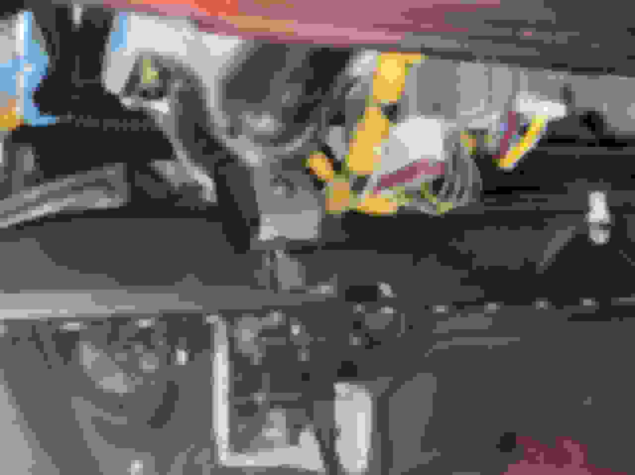
Step 7) Go to the passenger side of the car to the panel you removed, or remove it if you have not already. Behind it will be various connectors, etc. Below is what you're looking for. Unplug the grey connector (already unplugged in this pic) and you're going to plug your harness into the respective plugs, T'ing into the circuit. This is what triggers the LEDs to illuminate when you open the door. Next just undo the ground bolt above it, and put your grounding ring terminal there with the other factory ground terminals, and reinstall the bolt.
Before
After
Step 8) Now you're going to be tapping into the illumination circuit. This is what turns the footwell LEDs on with the parking/headlights on with both doors closed, but at half power. If you don't want this feature, you can simply skip this step. There's two ways to go about this. Honda provides you with a simple tap so you can tap the wire into the factory illumination wiring. I'm going to make a separate post once I wrap this up outlining the optional method. If you don't care about tapping factory wires, go for it, that's what Honda has you do anyway, I'm just personally not a fan, and there's a better way. See pics below for the instructed way to do this.
Wire you're using to tap into the factory circuit
Tap installed on wire
Wire you're looking for; red w/ black stripe
Tap fully installed
Step 9) At this point you're basically done. Just run the harness connections to their respective LEDs, snaking it through the panels you removed above, and zip tying it accordingly to secure it. I didn't take pics of this, because everyone will do it differently. The hard part has already been covered, the rest is just tidying up and reinstalling your plastics.
Here's some pics of the LEDs operating. Don't mind the wiring hanging out, I was just testing and mocking stuff up at this stage. The camera makes the LEDs appear much brighter than they actually are. Unfortunately these are pretty underwhelming, but for an OEM accessory they're.....cute? If you like OEM parts, get them. If you want some really serious footwell illumination, I'd just make your own with LED strips or other aftermarket modules, etc. It will be cheaper and brighter.
Driver/passenger side. Dome light off, door open, full power operation
Driver's side, door closed, headlights on. Half power, "ambient" mode.
Sorry for the shitty illumination pics, it's really hard to capture light output with a phone camera, best I could do guys, sorry.
That more or less wraps up this DIY. If you have any more specific questions feel free to ask. It's a pretty simple little kit, but it can be sketchy without instructions, so I figured I can clarify where everything goes / what everything does for the people nervous to tackle it otherwise. This DIY is more of a compilation of information from other sources, with my own input. Shoutout to the Japanese guy who documented his install, as well as @rossco for installing it himself and sharing his experiences.
Here's the OPTIONAL part of the DIY for people who aren't too keen on tapping wires, but would like to retain full functionality of the footwell kit. Another shoutout to @rossco for figuring this out. Didn't think about it myself, and feel like a fool for not doing so, but luckily someone else was on the ball.
Rather than tapping into the factory wiring for the illumination circuit, simply utilize the un-used illumination spade on the fuse box, or add it in to your wiring if you're already using it for gauges etc. Simply extend the short red/black wire on the footwell LED kit harness to reach all the way to the driver's side of the car. You'll need several feet of 20AWG wire. At this stage you can go as crazy as you want to extend this wire. Use a butt connector, or solder & heat wrap, un-tape the harness so you can run the wire within the corrugated loom in conjunction with the other wires & re-tape, or just leave it separate from everything. The sky is the limit on how cleanly you want to extend this wire.
To terminate the wire you can either use a bare spade terminal, or get fancy and crimp on the appropriate connector, a 1 pin Sumitomo HD 250, which you can buy from SOS or other sources. Here's two separate sources, you do you.
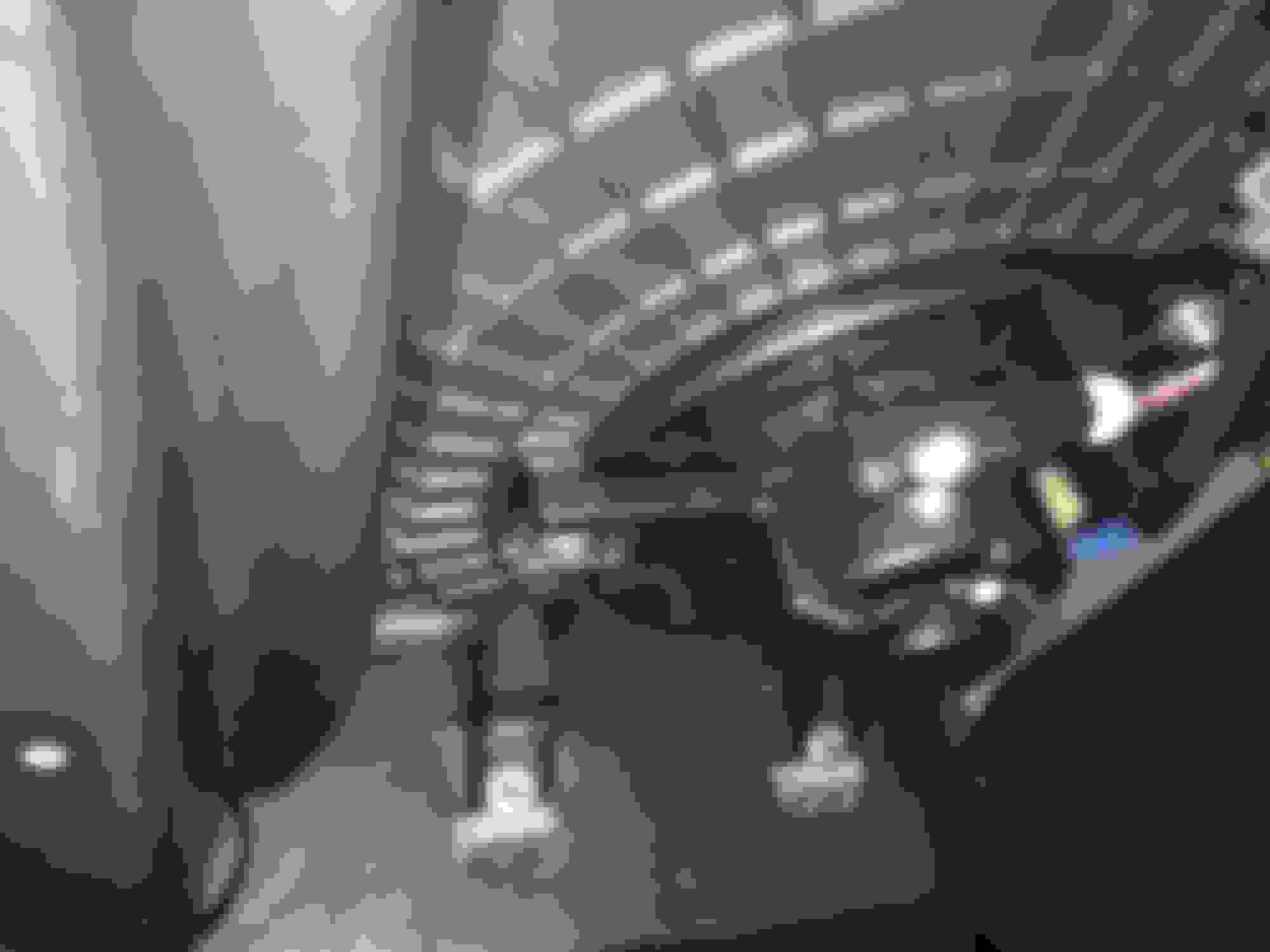
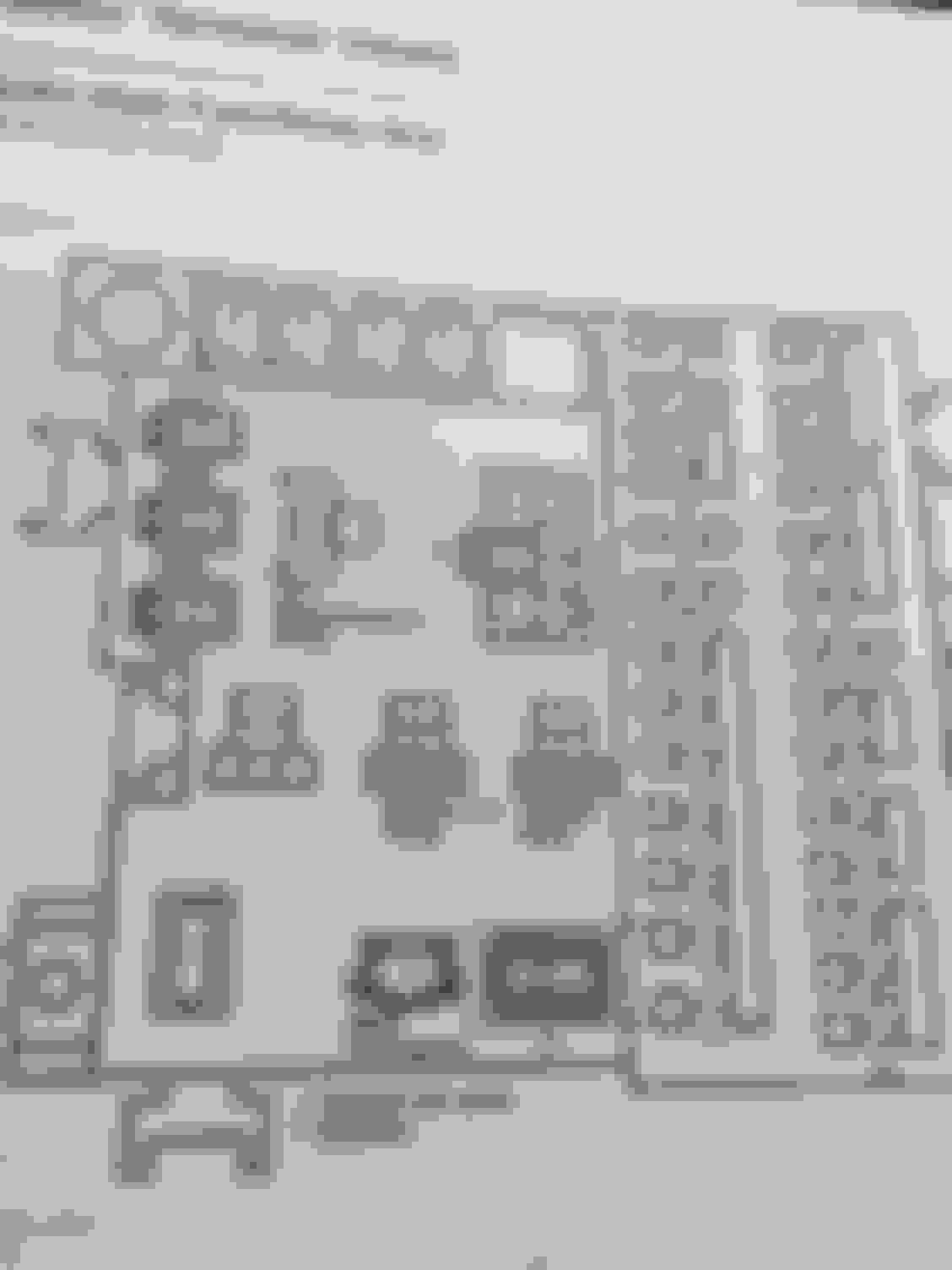
Once you've got your wire ready you're going to plug it into this spot on the under-dash fuse box on the driver's side. Credit to @rossco for the pics from the factory manual. This is the SAME circuit Honda has you tap into on the passenger side; same result minus the tapping.
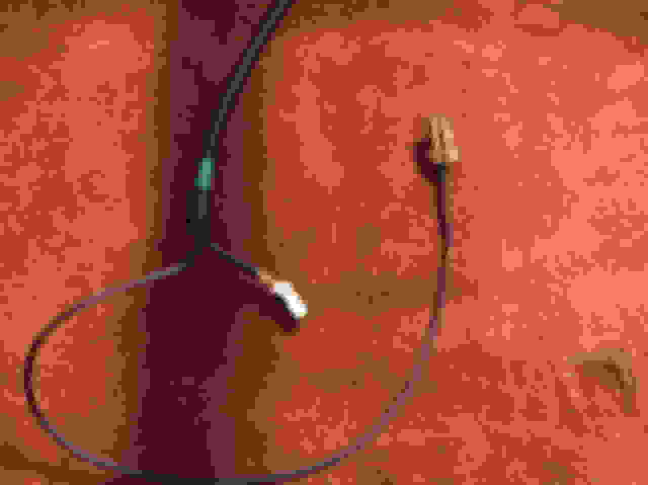
Here's my harness after I extended the red/black wire & terminated it. The length shown is basically what you need to extend beyond the plug for the driver's side footwell LED to plug cleanly into the fuse box.
You don't NEED to do this, I just think it's a better way than factory, but I can understand why Honda just chose to keep a majority of the harness integration where they did. Much simpler for your average DIYer or dealership to install, but for people who prefer to be a little more meticulous, there's a better way. Just giving you all options!
Thanks so much for doing this. I have been wanting to get around to installing the lights, and this will help.
What is the big silver screw for that came in the package with the lights? Anyone know? There is one large screw and 4 black screws. I know what the black screws go to but not the silver.
Thanks so much for doing this. I have been wanting to get around to installing the lights, and this will help.
What is the big silver screw for that came in the package with the lights? Anyone know? There is one large screw and 4 black screws. I know what the black screws go to but not the silver.
I'm assuming it was meant for the ground terminal lug. I just re-used the factory bolt; there was still plenty of length. I ended up not using the one supplied, it's HELLA long...
Also, of the 4 screws, 3 aren't pointy. I'm assuming the pointy screw is used to tap into the blower motor boss on the passenger side when mounting it using the bracket. It's too short to be used to mount the driver's side.
Ughh I should have looked at the black screws. It was tough screwing in the one to the blower - i bet i used the wrong screw. Oh well. Waiting on the HD 250 connector to come in. Will update once everything is done.
I purchased a couple of blue LED lights at Walmart that had the 12V plugin the auto dept. The LEDs were small black plastic smoothed cubes 1/2 the size of a sugar cube. I cut off the 12V plug and added a "Add a circuit" auto fused plug in to the circuit that powers the 12V plug below the secret compartment. That way the lights are always on when the key is in and rotated to the accessory or run position. I ran the pax light wire behind the headunit. The soft blue glow adds a nice feel at night. Easy and inexpensive. Been running without issue for about 8 years now.
A friend in Japan helped me order a few of these kits and he included the instructions (I assume the Honda dealer gave it to him). I've scanned it for those curious:
What side of the car is the red/black wire on? Passenger or driver? Instructions above say passenger, but my passenger side does not look like the photos.
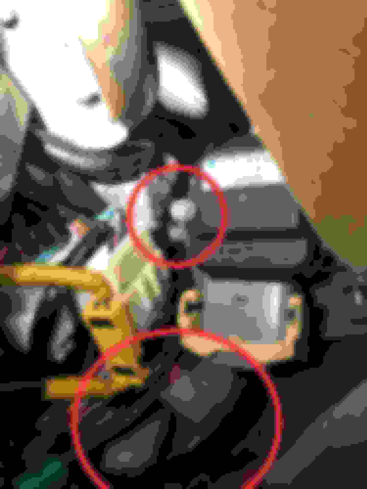
This is what it look like above the passenger side kickpanel. I’ve circled the ground as well as the two plugs that go from the LED wiring harness into the factory harness. I had to remove the Keihin part as well as the bracket just to get to the factory ground point. It was tight in there and a real pain in the ass to get to.
As far as the illumination wire coming off the LED harness, it the perfect length to go into the factory harness behind the passenger kickpanel, but that harness does not have a red/black wire.
 10-06-2020, 04:51 AM