Stock 02 sensor grounds with Aem Ecu V2
#1
When i installed my aem uego i cut one 02 sensor and taped it up. i left the other sensor in tact and taped them both up near the trans. One day while i was under he car i cut the other sensor off and cut the 8 total wires shorter. after that car voltages were ****ed throttle and load were maxed out etc. it was obviously electrical. i finally figured out that somehow these grounds are needed from the stock 02 sensors? i have both the grounds grounded temporarily in the same spot. power and heater wires are just taped. car seems fine but my 02 value when shut off went from 17.9 to 17.7 or17.8. so im wondering how much of my tune is off or what the interference is. Is there any way i can disable these old sensor wires. any information greatly appreciated. not really sure if my 02 is reading correctly now so im taking it easy until someone can help me understand why these grounds need to be grounded if the sensors arent used.
#2
any help will be greatly appreciated guys. I can unplug one of the oem 02 sensors without any issues but the other one needs to be grounded for car to start, not read full load and throttle etc. any ideas could really help me out considering im being told i should be able to just unplug both.
#3

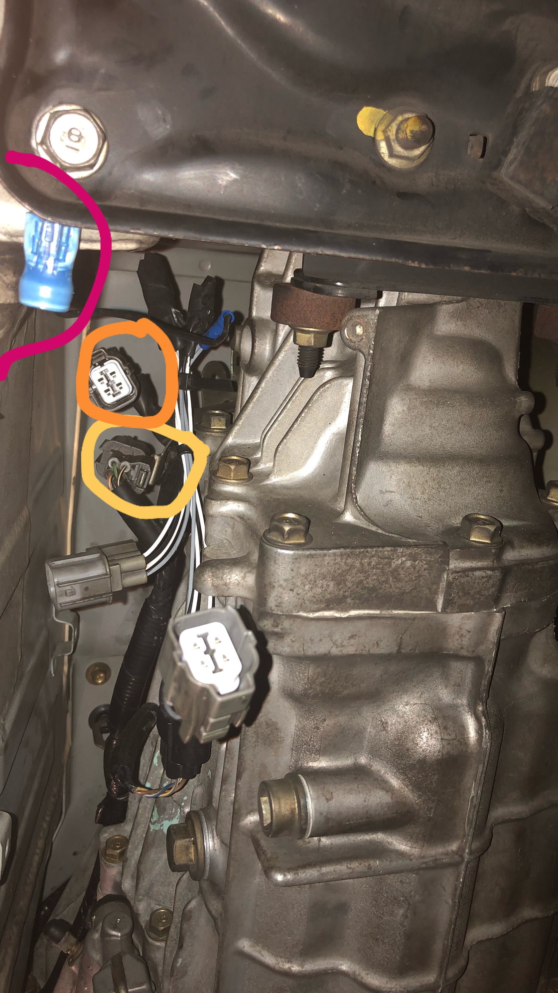
ok so PINK is the temporary ground to get this pos running. i used both grey wires (grounds) from 02 sensors to ground even though i only needed the one. ORANGE is the sensor that im pretty sure normally sits on passenger side of trans. this is the one that needs to be plugged in and grounded or car freaks out. YELLOW is the sensor normally mounted on driver side and is the one that i can plug in or take out it doesnt matter at all. Please someone explain wtf is going on.
#4
no one has any ideas of why i seem to be the only s2k who cant unplug their old 02 sensors using aem v2 ecu?
i might have touched the wires together and sparked somethig i definitly grounded the wires on accident because i didnt know they were still live. maybe this reversed the voltages for tps and map? i have little to no idea honestly how electricity works. i wired up my entire car for everything as far as sensors, guages, fuel pump relay, switches etc. but not really sure why these voltages are needing this ground.
i might have touched the wires together and sparked somethig i definitly grounded the wires on accident because i didnt know they were still live. maybe this reversed the voltages for tps and map? i have little to no idea honestly how electricity works. i wired up my entire car for everything as far as sensors, guages, fuel pump relay, switches etc. but not really sure why these voltages are needing this ground.
#6
Hey, so I looked at the wiring diagram.
When you say an O2 sensor has to be grounded for it to work, does part of the O2 itself need to be touching metal? Or does it work with the O2 just hanging there?
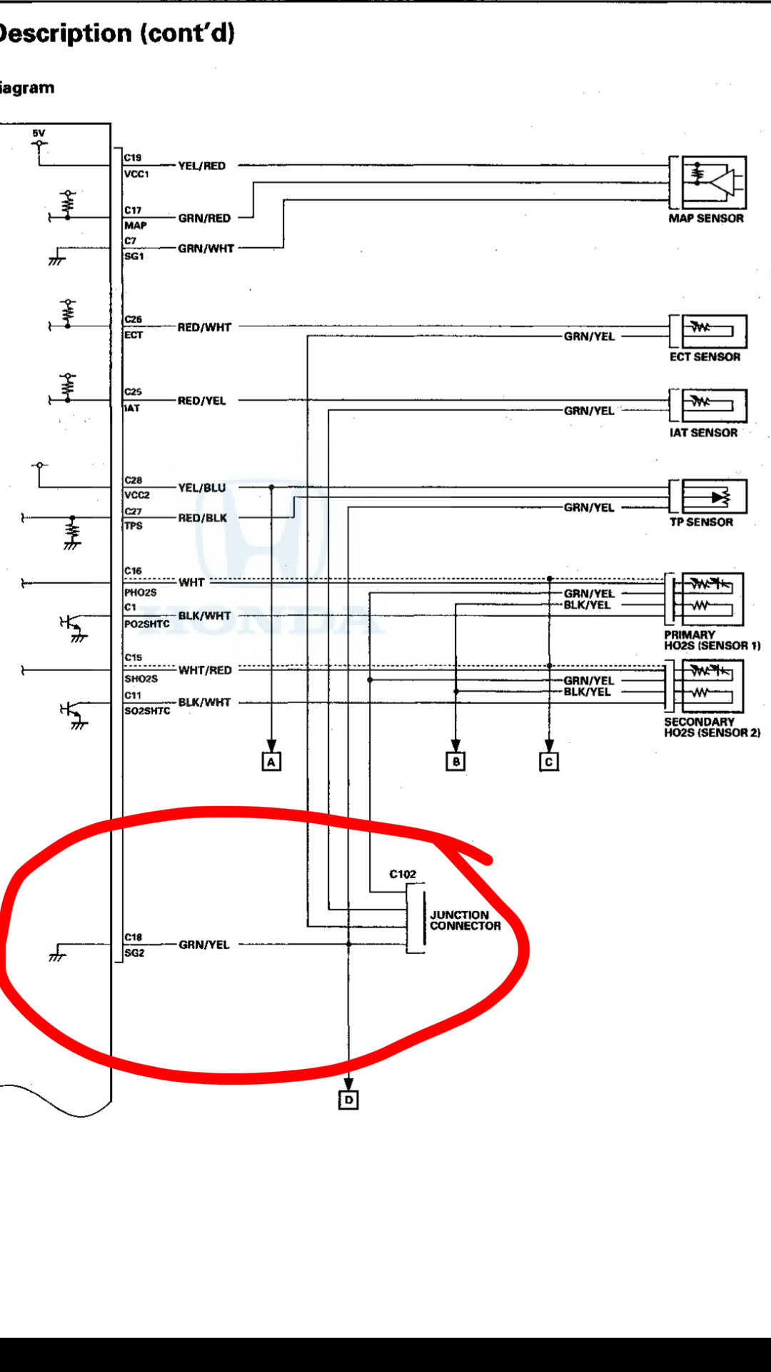
If the O2 sensor needs to be touching metal, my thoughts are a break in the wire between junction c102 and SG2 (ECU pin c18). I'll attach a pic of the diagram with it circled later. My phone doesn't want to add the attachment...
This could explain the sensors like tps going wacky (since the ground would be "floating"). Normally there's no ground through the O2 sensor as SG2 is the dedicated ground for these sensors.
If there's a break in the wire to SG2, electricity is going to have to find another way to ground, in your case it seems thru the O2 sensor body.
Last edited by mikeyds; 06-19-2018 at 10:44 AM.
#7

OK, circled above is the wire I'm talking about. Possibly there could be a break in that wire.
For the sensors to read accurately it's important they are connected to this dedicated signal ground.
To test for a break in the wire you will need a multi-meter, use the continuity setting (see the link if you're unsure what that is). Make sure the O2s are unplugged.
One multi-meter probe on ECU pin C18, the other probe in one of the body-side O2 sensor plugs, probing the green/yellow wire.
You can also probe between pin C18 and the green/yellow wire coming out the TPS. The O2 sensor and TPS use the same signal ground.
If things are correct you should see continuity (the meter beeps) between those connections.
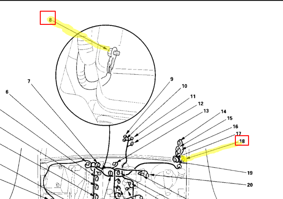
If there is continuity in that test, maybe the ECU itself has an internal problem, or another connection is missing between the ECU and car chassis for ground. There is a ground behind the engine (#8 in below pic) which is important.
If there is NOT continuity in that test, check the junction C102 connector up under the dash (#18 below). It's a 20 pin. Maybe its unplugged?

Both of those can be rather difficult to locate. I tried to find #18 on my car but it's too dang hot today.
Last edited by mikeyds; 06-19-2018 at 10:37 AM.
Trending Topics
#8

OK, circled above is the wire I'm talking about. Possibly there could be a break in that wire.
For the sensors to read accurately it's important they are connected to this dedicated signal ground.
To test for a break in the wire you will need a multi-meter, use the continuity setting (see the link if you're unsure what that is). Make sure the O2s are unplugged.
One multi-meter probe on ECU pin C18, the other probe in one of the body-side O2 sensor plugs, probing the green/yellow wire.
You can also probe between pin C18 and the green/yellow wire coming out the TPS. The O2 sensor and TPS use the same signal ground.
If things are correct you should see continuity (the meter beeps) between those connections.
If there is continuity in that test, maybe the ECU itself has an internal problem, or another connection is missing between the ECU and car chassis for ground. There is a ground behind the engine (#8 in below pic) which is important.
If there is NOT continuity in that test, check the junction C102 connector up under the dash (#18 below). It's a 20 pin. Maybe its unplugged?

Both of those can be rather difficult to locate. I tried to find #18 on my car but it's too dang hot today.
BRO THANK YOU. i kind of figured it had to do with ms touching the wires together. im not 100% sure of how im going to do this but i will definitly take a look this weekend or when i get time. even if i can take it to a shop and show them this to save time. I will let you know when the issue is fixed and if that wS the problem
#9
Ok so i just got done checking continuity and it turns out the wires are fine. So i must have shorted the sensor ground itself in the ecu. for now i will continue to ground it theough the chassis and worry about it later. turns out i wired my 02 sensor to a sensor ground on D connector so one day i will move the c18 wire and add it to the D sensor ground and that should fix it.
#10
update for anyone who shorts a sensor ground. talked to aem and i thought each plug had its own ground circuit for its sensor grounds however i was incorrect. theyre all on the same circuit. so you short one, you shorted them all. im going to send my ecu in to be fixed and then i should be able to ditch the chassis ground i had to make. if you think you shorted the sensor grounds, id say just add a chassis ground and if it seems fixed send in the ecu so you get proper readings. thanks for everyones help. i swear electrical issues are the worst.
Thread
Thread Starter
Forum
Replies
Last Post
hyperpm
S2000 Under The Hood
5
05-26-2003 07:15 PM


