
Boost a Spark NOT working like planned?
 07-11-2013, 06:11 AM
#1


I am going to write up a little DIY install for the Kenne Bell Boost a Spark but have a question about the ignition coil wire. The goal is to find that ONE power wire that feeds all 4 coil wires. There is little to no room in the engine bay to find that 1 wire in the harness so I looked under the dash. In the helms it states that this wire is located under the dash at the fuse panel in the #4 slot. I cannot for the life of me find a single black/yellow wire that goes into the harness through the firewall. I did find one but that wasnt it. It was connected to two plugs coming from the fuse box.
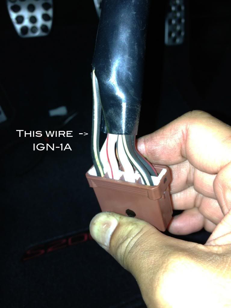
In the helms diagram it shows all 4 coil wires tying into 1 single wire to the fuse box and then going to the ignition switch. The wire remains the same color black/yellow at IGN-1A. I pulled the plug off the fuse box where it shows this going to and the wire is thick and black/yellow. Is this the wire you can use to power all 4 coils? I really don't want to cut this wire if it's not 100%. There is another black/yellow wire in this plug but and its labeled IGN-1B which is probably the other side of that circuit.
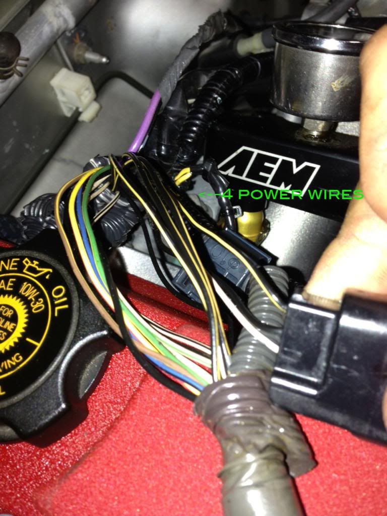
The other way to do it would be to go directly to the harness on top of the motor where all 4 coils are at and then there would be no guessing. It takes a little more work dealing with 4 wires but at least there would be no doubt.
Once I figure out which wire I'm going to use, I will proceed with the install.
In the helms diagram it shows all 4 coil wires tying into 1 single wire to the fuse box and then going to the ignition switch. The wire remains the same color black/yellow at IGN-1A. I pulled the plug off the fuse box where it shows this going to and the wire is thick and black/yellow. Is this the wire you can use to power all 4 coils? I really don't want to cut this wire if it's not 100%. There is another black/yellow wire in this plug but and its labeled IGN-1B which is probably the other side of that circuit.

The other way to do it would be to go directly to the harness on top of the motor where all 4 coils are at and then there would be no guessing. It takes a little more work dealing with 4 wires but at least there would be no doubt.

Once I figure out which wire I'm going to use, I will proceed with the install.


 07-11-2013, 08:10 AM
#4

I cut the 4 coils at the top and joined them into one, then connect to the IN of the BAS, then the OUT on the BAS is then split back to the coil power wires.
If you are able to find the No.4 15amp BLK/YEL wire at the fuse box and splice it there, this could be better solution because you minimize the risk of cold solder joints.
If you are able to find the No.4 15amp BLK/YEL wire at the fuse box and splice it there, this could be better solution because you minimize the risk of cold solder joints.
07-11-2013, 11:29 AM
#5
Yeah I agree but the challenge is finding that damn wire. If the thick wire in the first pick is the one to use then it would be perfect but if its not...then I gotta resolder it back to normal.
The way the helms lays out the diagram, that wire should be it because its right color along with label IGN-1A. I want to find the one going from the fuse box to the engine bay but I'm starting to think its not wired like that. It's very hard to find were all 4 wires combine to 1. If its in the harness between the engine and firewall, that ain't happening because there is no room to work. I think I will do the 4 wires directly off the coil. Then there's no doubt and I have way more room to work with.
The way the helms lays out the diagram, that wire should be it because its right color along with label IGN-1A. I want to find the one going from the fuse box to the engine bay but I'm starting to think its not wired like that. It's very hard to find were all 4 wires combine to 1. If its in the harness between the engine and firewall, that ain't happening because there is no room to work. I think I will do the 4 wires directly off the coil. Then there's no doubt and I have way more room to work with.
07-12-2013, 12:04 AM
#7
Registered User

Join Date: Feb 2011
Posts: 1,658
Likes: 0
Received 0 Likes
on
0 Posts
Trending Topics
07-13-2013, 07:52 PM
#8
So that didnt work worth a shit. My question is why?? I installed it under my dash so the wire lengths are around 3-4 ft per wire. I cranked it all the way up even at .019 gap and it still blew out my spark around 26-28 psi like before with coils only. I even ran it full time and I know it was working because when I turned it up at idle I started to see AF change and gauges dimmed a tad big in and out.
I would think this thing should have a damn relay ran to it or else it's only only amplifying and already weak signal. What are your thoughts??
I would think this thing should have a damn relay ran to it or else it's only only amplifying and already weak signal. What are your thoughts??