2005 turbo setup
#1
I haven't been on these forums for a long time, but I have always owned a Honda. Last April I had an opportunity to finally pick up a nice Honda, a 2005 silverstone s2000. I always had the intention of having a turbo setup on the car, and the car is pretty much finished. I figured I would share the build and give back. Thanks to the people that post their failures and successes. Without that, the process becomes a lot more challenging. I have a lot of pictures, and hopefully I can explain most of what I did. Please don't hesitate to ask any questions.
After doing a bit on research on here (as well as a few other places), I planned out my setup around a PTE journal bearing 6262, garrett gt intercooler core, and tial wastegate/vent valve. I have had a turbo setup on a honda (94 civic) before, but as with every different chassis, some things are easier....some more complicated.
I wanted a nice sized turbo capable of decent power numbers at a low pressure level (I would like to keep boost in 1st and 2nd limited). After scouring completed setups, I decided to use a short runner pipe topmount manifold with a decent collector. I had a welder from when I worked on the civic, so I started removing parts so I could start mocking things up.


Battery and fusebox relocation was going to make it easier to locate the turbo and not worry as much about heat. The power steering assist box stayed in the factory location though.
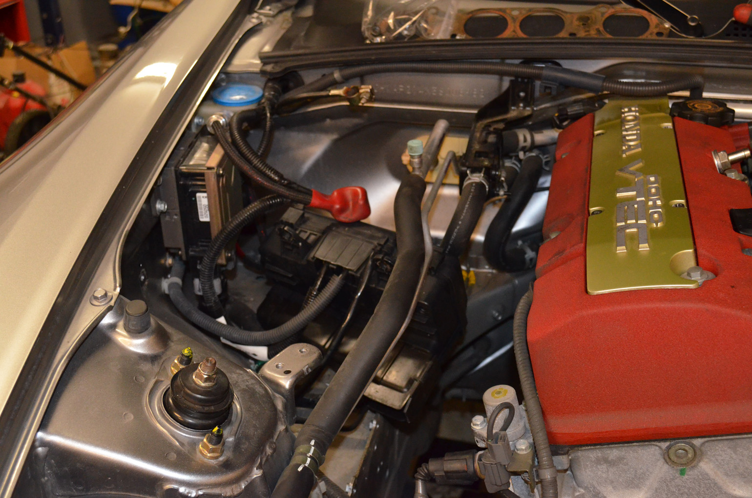
Air pump, lines, etc. were removed since I am using an AEM V2 ems.


I also opted for an oil cooler, as I would be removing the stock cooler. I picked up a 19 row mocal, so far it seems to have worked nicely.
The main bracket wasn't too bad to make...but was not stable enough on the latch support, so I made a simple angle to tie the opposite side of the cooler to the car. The a/c accumulator stayed in its factory location. I purchased the aftermarket flex lines from a vendor here, and am very happy with them.


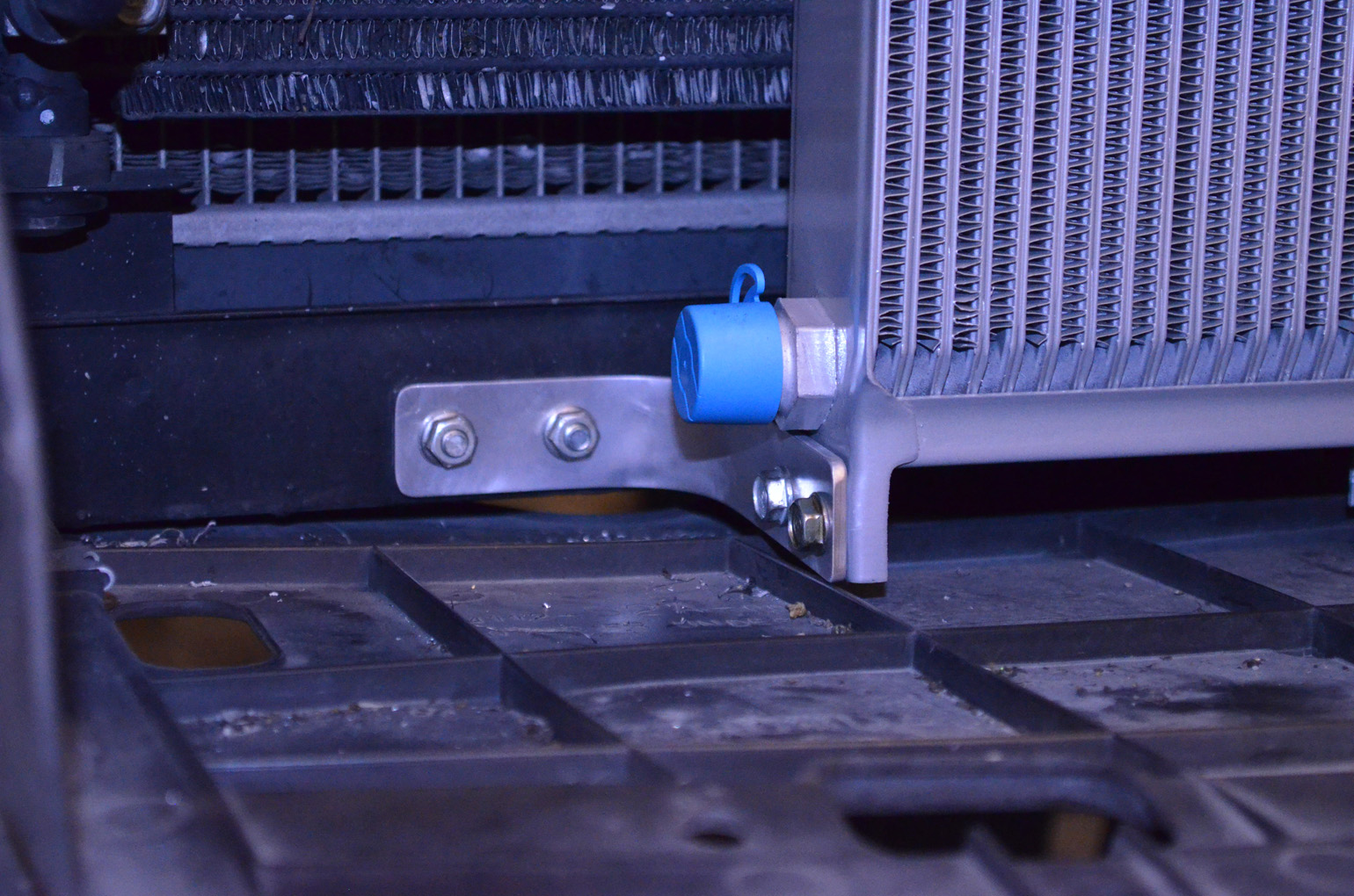

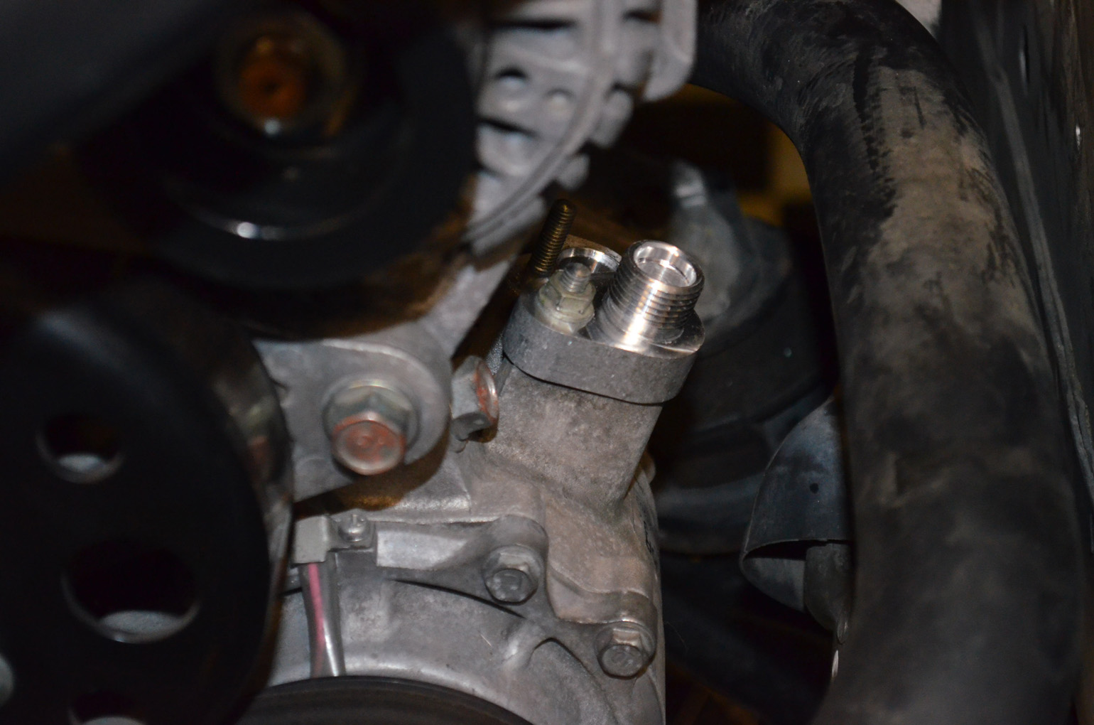

My oil cooler lines...I used pushlock style lines and was worried about the oil pressure and leakage. So far they have held up very well.


I made my own heater core hose/valve relocation bracket with some aluminum angle. I also bought a couple different hoses and turned them to where they would not kink because of excessive bending.

While I was taking things out of the engine bay, I decided to remove and clean the intake manifold. It was not too dirty/oily.
I also tapped and plugged the water circuit to the IACV valve / throttle body.
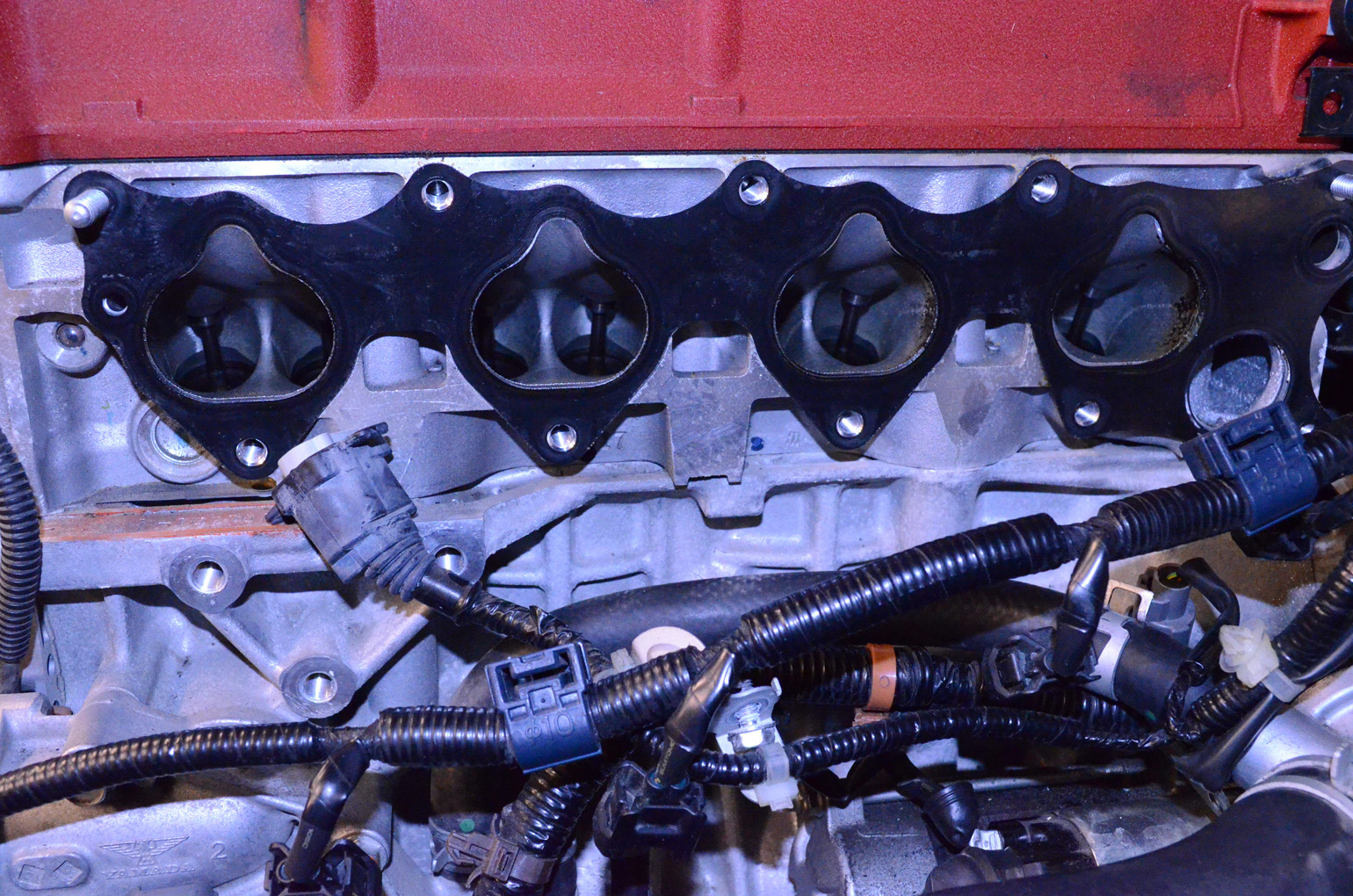

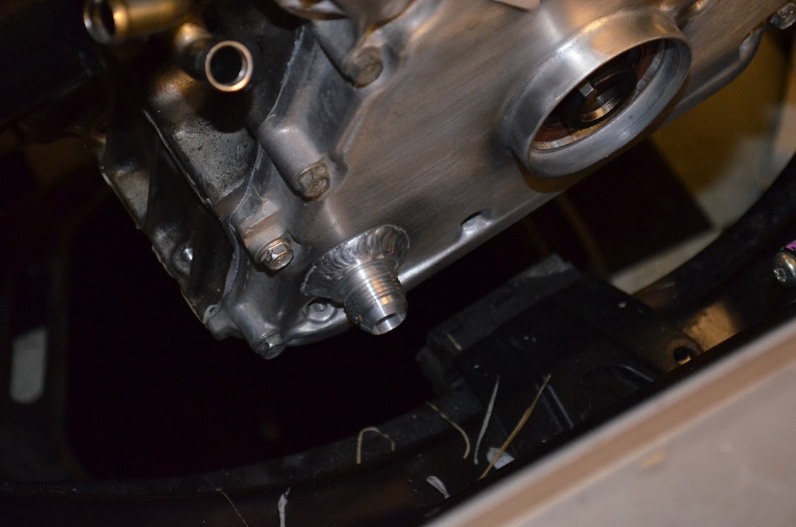
I decided a timing chain cover-return would work the easiest for me. If I could do it again, I would locate it just a little bit higher.


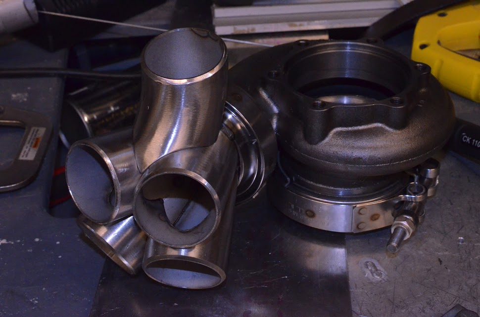
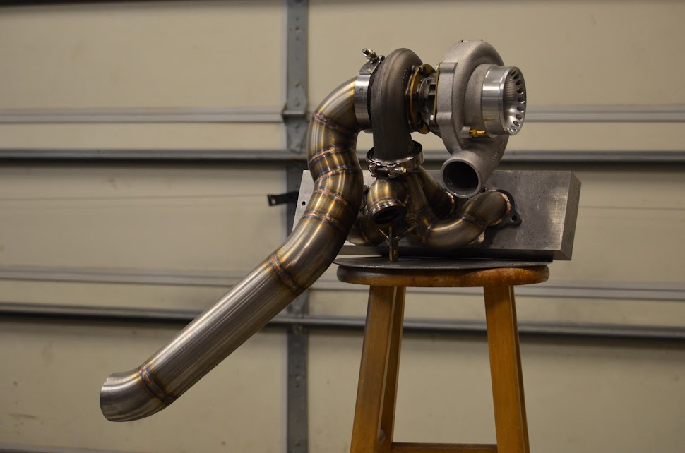
Onto the manifold. When making this I wanted to keep the turbo somewhat low, and that made the runners incredibly short for cylinders 2-3. I worry about reversion and also about it not being equal length. I have to run conservative timing to not get knock spikes. I believe with a longer, more equal length manifold I could increase timing. Maybe down the road.......


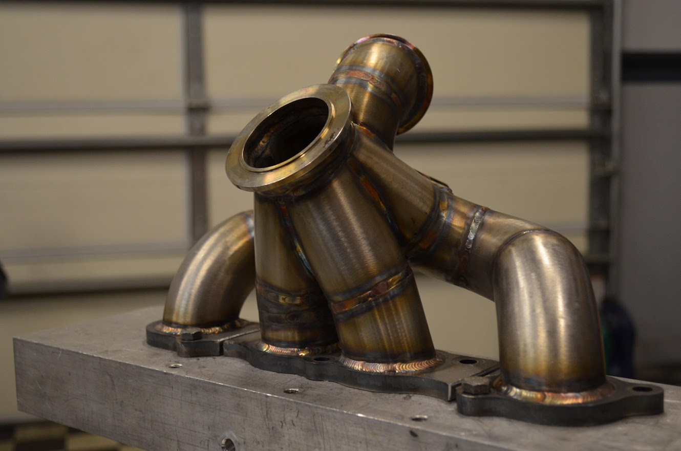
Final product. Disregard the mounting tab.....I had made it hoping to help support the manifold/turbo. It did not work out. I don't think the bottom half of the mount was flexible enough, and that the turbo hanging off the motor was vibrating at a different speed than the mount location was. It pretty much tore the wastegate neck off after a few thousand miles.
Also the vband clamp for the wastegate comes close to the frame on the car.....I would say about .7-.8". I am using stock mounts now and haven't heard/felt anything coming in contact with the chassis.


After doing a bit on research on here (as well as a few other places), I planned out my setup around a PTE journal bearing 6262, garrett gt intercooler core, and tial wastegate/vent valve. I have had a turbo setup on a honda (94 civic) before, but as with every different chassis, some things are easier....some more complicated.
I wanted a nice sized turbo capable of decent power numbers at a low pressure level (I would like to keep boost in 1st and 2nd limited). After scouring completed setups, I decided to use a short runner pipe topmount manifold with a decent collector. I had a welder from when I worked on the civic, so I started removing parts so I could start mocking things up.
Battery and fusebox relocation was going to make it easier to locate the turbo and not worry as much about heat. The power steering assist box stayed in the factory location though.
Air pump, lines, etc. were removed since I am using an AEM V2 ems.
I also opted for an oil cooler, as I would be removing the stock cooler. I picked up a 19 row mocal, so far it seems to have worked nicely.
The main bracket wasn't too bad to make...but was not stable enough on the latch support, so I made a simple angle to tie the opposite side of the cooler to the car. The a/c accumulator stayed in its factory location. I purchased the aftermarket flex lines from a vendor here, and am very happy with them.
My oil cooler lines...I used pushlock style lines and was worried about the oil pressure and leakage. So far they have held up very well.
I made my own heater core hose/valve relocation bracket with some aluminum angle. I also bought a couple different hoses and turned them to where they would not kink because of excessive bending.
While I was taking things out of the engine bay, I decided to remove and clean the intake manifold. It was not too dirty/oily.
I also tapped and plugged the water circuit to the IACV valve / throttle body.
I decided a timing chain cover-return would work the easiest for me. If I could do it again, I would locate it just a little bit higher.
Onto the manifold. When making this I wanted to keep the turbo somewhat low, and that made the runners incredibly short for cylinders 2-3. I worry about reversion and also about it not being equal length. I have to run conservative timing to not get knock spikes. I believe with a longer, more equal length manifold I could increase timing. Maybe down the road.......
Final product. Disregard the mounting tab.....I had made it hoping to help support the manifold/turbo. It did not work out. I don't think the bottom half of the mount was flexible enough, and that the turbo hanging off the motor was vibrating at a different speed than the mount location was. It pretty much tore the wastegate neck off after a few thousand miles.
Also the vband clamp for the wastegate comes close to the frame on the car.....I would say about .7-.8". I am using stock mounts now and haven't heard/felt anything coming in contact with the chassis.
#2
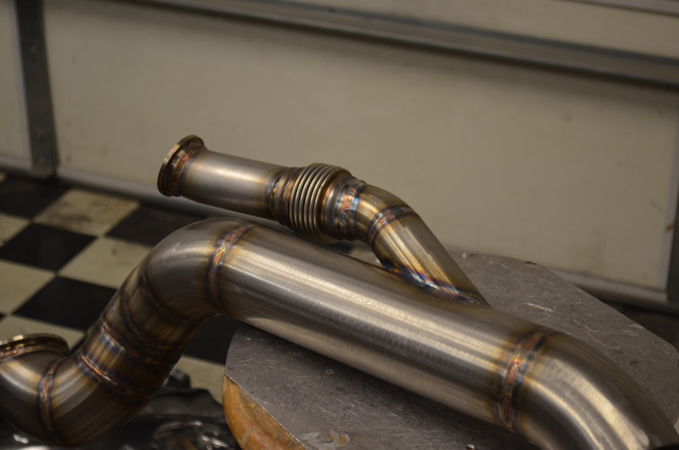
I decided to recirculate the wastegate dumptube. I grew to like just hearing the sound of the turbo. I'd find out that this single 44mm would not hold the boost that I wanted (5-6psi).....and adding another recirculated gate after the fact, was a huge pain. Also would have liked to make the downpipe with less pieces, but it is what it is.


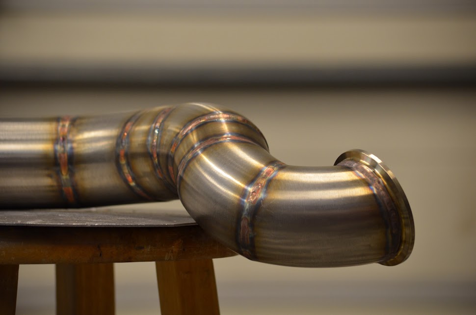

Another note...I flushed the first dump (with the flex) to the downpipe. I wish I thought about it more and ran the dumptube into the downpipe a little bit, to help it draw out of the wastegates. The 38mm dump I added later, protrudes into the downpipe, and has a worse angle for the exhaust to flow out IMO. However when I tested the gates individually, the 38 held the creep a tad better than the 44.




I have more pics...but its getting late, will post sometime tomorrow.
Thanks for looking.
Another note...I flushed the first dump (with the flex) to the downpipe. I wish I thought about it more and ran the dumptube into the downpipe a little bit, to help it draw out of the wastegates. The 38mm dump I added later, protrudes into the downpipe, and has a worse angle for the exhaust to flow out IMO. However when I tested the gates individually, the 38 held the creep a tad better than the 44.
I have more pics...but its getting late, will post sometime tomorrow.
Thanks for looking.
Trending Topics
#8
I did have the car on the dyno about a month ago. I'll post the graph when I get back from work, but the peak numbers were 391 / 259 @ 10psi. The torque curve is pretty flat from 5500 to 8300, only varying about 10 ft lbs. Powerband is very gradual/smooth.
#10
On to more turbo parts.
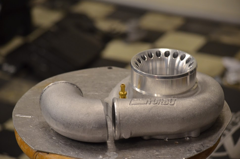
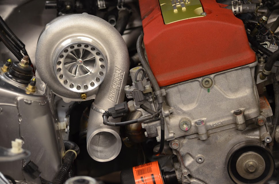
I decided to modify the outlet of the compressor housing using a 2.5" cast elbow. I don't like couplers, and when I have to use them I'd rather use a straight coupler if I can.


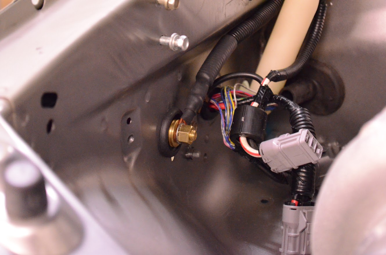
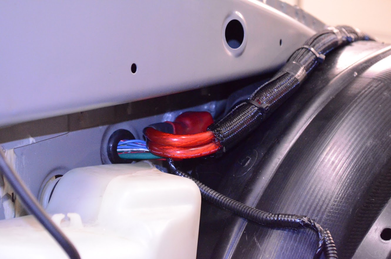
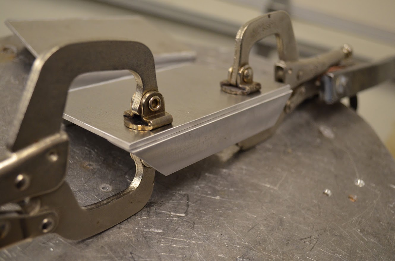
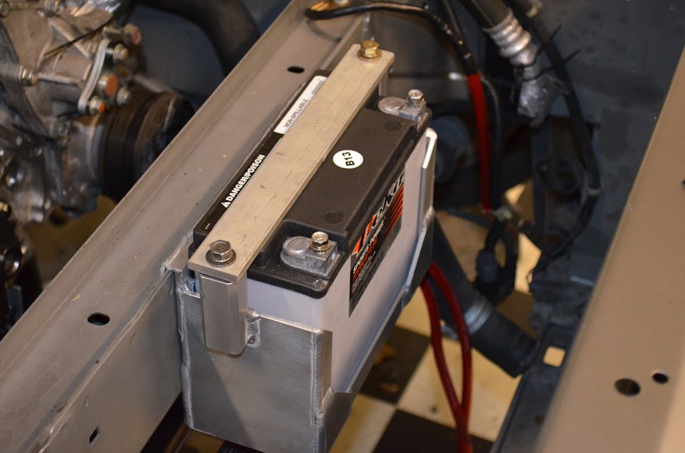
Moving the harness inside the fender. I decided it would be easier to keep the battery in the bay. I bought a medium sized deka battery to mount on the crossbrace, and ran power wire through the fender to a junction under the power steering box.





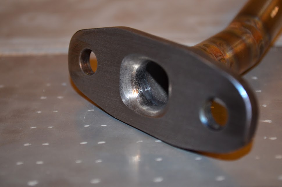
Here is the oil return outlet tube.

I decided to modify the outlet of the compressor housing using a 2.5" cast elbow. I don't like couplers, and when I have to use them I'd rather use a straight coupler if I can.
Moving the harness inside the fender. I decided it would be easier to keep the battery in the bay. I bought a medium sized deka battery to mount on the crossbrace, and ran power wire through the fender to a junction under the power steering box.
Here is the oil return outlet tube.


 Regarding what you said about runner length, why didnt you run cylinders 2 and 3 to the collector away from the motor so you could get them closer to the length of 1 and 4?