When you click on links to various merchants on this site and make a purchase, this can result in this site earning a commission. Affiliate programs and affiliations include, but are not limited to, the eBay Partner Network.
I bet you're seeing this post and asking why? There's a whole bunch of posts on the benefits and cons of a K Swap versus the F20/F22. I don't want to get in the weeds with this and hope this can just be a very detailed guide of how I K-Swapped my S2K.
This is my 2002 AP1.
Original F20C1 - Or so I thought
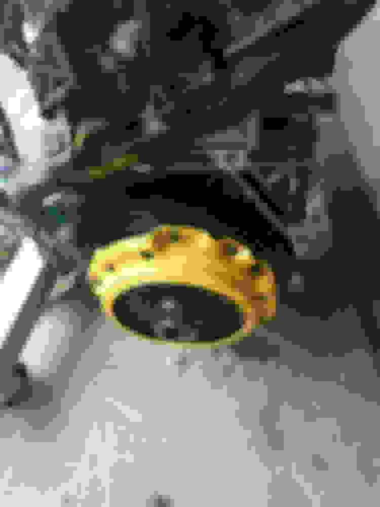
I started noticing symptoms of a leaking head gasket. I gathered the rebuild parts and began to tear the head off. Once I got the head off I noticed a little something off about the pistons. I noticed they weren't original and were replaced with JE Pistons. Diving deeper that means the cylinder walls were sleeved. This means that the engine had been out before and was not original.
Looking at the head, I could now see why it wasn't sealing.
It most likely overheated and warped the combustion chamber. There was also tons of buildup on the valves.
Well, I was planning on K-Swapping my very first car, a 1985 Honda Accord LX. I even had the K20A2 already installed in it, but I thought the S would be a better candidate for it.
So, I decided to pull this out and begin the S2K20 Build. The Accord will have to wait.
I'm going to post each step as a new post. Next up F20 Removal
Alright time to take this tired engine out.
Disconnect and remove the battery.
Drain coolant from the radiator and engine block. Drain oil from engine.
Disconnect the VSS sensor and back-up light switch from the transmission. Unbolt the prop shaft from the rear of the transmission. Disconnect both O2 sensors. Crack the bolts that join the transmission to the block (should be able to reach them all without dropping the subframe with the head removed). Unbolt the starter bolt that connects to the transmission. Disconnect the 3 bolts from the rear transmission mount to the body. Lower the engine subframe. Put a jack under the transmission and remove the bolts that join it to the engine. Slide the transmission towards the rear of the car to remove the input shaft from the throwout bearing. Lower the transmission on the jack and roll out from under the car.
I already had the Intake and Exhaust Manifolds disconnected to take the head off. Relieve fuel pressure, disconnect the fuel line to the fuel rail on the intake manifold, remove the injector plugs, ground wire, coolant temp sensor, TPS, MAP, and IAT sensors, and remove the coolant lines then take the intake manifold out. I left the exhaust manifold connected for now.
Disconnect the rest of the sensors on the engine block and swing the engine harness out of the car on the drive side. Remove the rest of the coolant lines at the engine.
Unbolt the A/C Compressor from the engine and swing out of the way. Best option is to have the refrigerant in the system pumped out at a shop and then remove the compressor and lines completely, but I just thought I was doing a head gasket.
I lifted my engine out of the car, but if I had a car lift or enough clearance on jack stands I would have disconnected the power steering rack at the tie rods and totally dropped the whole subframe. For lifting the engine out, get the hood up high or take it off completely.With the engine strapped and attached to the hoist, put tension on the strap and removed the engine mounts. I belly strapped the engine and had a friend help me jimmy it out. In hindsight, I also would have loved to have a engine hoist leveler as that would have kept me from having to remove the front bumper to have enough reach. Lessons learned.
Once out disconnect the rest of the wire harness connectors in the engine bay. Open up the kick panel under the dash on the driver side just inside the door. Disconnect the wiring harness connectors from the ECU. Remove the ECU. Feed the wiring harness through the fire wall at the rubber grommet. Remove the whole engine harness from the car.
Now would also be a good time to remove the exhaust manifold from the car.
Block and open holes into the car (firewall) and tape up any loose connectors. Give the engine bay a good degrease and wash down.
Alright these are all the parts I used and you will most likely need. As I said before I already had a K20A2 out of a 2004 RSX Type S, that came with the ECU, wiring harness,charge harness, and transmission (not needed). Below is a full parts list with the prices I paid. I hope to recoup a little from the transmission and eventually the F20 after I rebuild it. I also recommend spending a little more and buying a K-Tuned swivel thermostat
So you don't have to do the math Grand Total: $5,798
Money saving options:
Go with a cheaper K-Engine or buy a whole parts car
Make your own conversion harness
Make your own K2F engine-transmission adapter plate out of 1/2" thick aluminum
Use connectors from S2000 harness (not recommended) or get a full harness from Rywire or others
Cut exhaust manifold flange off of K20 and re-use
Make your own engine adapter plate to use stock engine mounts(I had a ripped S2000 one or I would have done this)
Doing all this I think this could be accomplished for ~$3600, but I'm happy with the options I have.
I started by removing the pressure plate, throwout bearing, and clutch from the F20.
Then I started on the K20 prep. First, I had to separate it from the transmission. Then remove the pressure plate, throwout bearing, clutch, and flywheel. Install the Clutch Masters K2F Flywheel, S2K Clutch (use clutch pin), S2K throwout bearing and S2K pressure plate.
With that complete, I pulled the water pump off to replace all the seals (not necessary, but recommended). I then removed the thermostat , the thermostat case, and the water passage.
Clean the water passage and re-install with fresh liquid gasket and a new o-ring. Re-install the water pump with a new gasket. Install the thermostat case with a new gasket. Lastly, the thermostat needs to be replaced with one with a swivel neck because the current orientation is pointed away from the radiator where the hose connects. K-Tuned and others make these. Once again, use a new gasket.
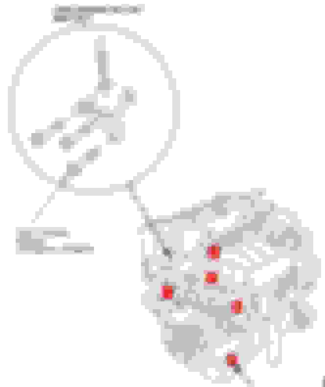
Next, remove the heater outlet pipe, located to the left of cylinder 4 on the exhaust side, and install a plug (I got mine from K-Tuned). After that, remove the water outlet, located to the right of cylinder 4 on the intake side.
Remove the alternator (A)for better access when installing the intake manifold. Remove the AC compressor (B). Remove the power steering pump (C) because it is not needed. In its place will go an idler pulley, because I am keeping AC. Remove the tensioner pulley bracket (D). Remove the Side Engine Mount Bracket (E) located on the crank pulley side of the engine next to the tensioner bracket.
With that removed, install the JSP Fab version 1 K series to F series Intake Manifold Adapter onto the head. Do not use a gasket yet, as you will need to drill and tap some holes. Follow the directions on their web page JSP Fab K2F Intake Adapter v1 Instructions . After test fitting the manifold, remove the manifold and the adapter. Install a new water outlet o-ring in the adapter plate, use a new K20 intake manifold gasket and then bolt on the adapter plate. Leave the intake manifold off.
Remove the alternator for better access when installing the intake manifold. Remove the AC compressor. Remove the power steering pump because it is not needed. In its place will go an idler pulley, because I am keeping AC. Remove the tensioner pulley bracket.
Install the K-Engine to F Transmission adapter plate. Install the bolts labelled K with the bolt heads on the engine side. Install these loosely until transmission is in place. (Sorry I'm missing the lengths on the bottom 3 bolts. I'll measure and edit this)
Lastly, install the engine mount brackets on the engine. I used Hasport's APK2 kit. Intake Side Exhaust Side
Now the engine is ready to be installed in the car.
Following your build closely as I'm planning to this swap in the near future. Thank you for taking the time to post detailed pics and write up. Keep them coming!
Remove exhaust manifold from the midpipe (if not already removed).
Remove engine mount stiffener from subframe. Engine Mount Stiffener
Install engine mounts loosely. Bolt into place with supplied bolts and washers through the underside of the subframe (1 per side).
Engine Mount
Clear any wiring or coolant hoses in the engine bay to keep them from getting pinched. Now you're ready to lift the engine into place. Attach your hoist to an engine leveler in a similar fashion.
F20 Lifting Diagram
The RSX mounting locations are slightly different as we won’t have a transmission already installed. Use the below mounting location on the front (crank pulley side) and one of the K20 adapter plate bolts on the transmission side of the engine.
K20 Front Engine Lifting Point
Lower the engine into place and slot the engine mounts into the brackets. Use correct bolt hole on APK2 bracket based on your engine (lower holes for K20) and install through-bolts with washers and nuts.
Lower the front subframe (if it isn’t already). Put board across front subframe bar and oil pan and place a jack under it. Remove the middle subframe bolts. Un-thread the outer transmission bolts 3 inches lower. Lower the jack until the subframe settles on the bolts.
Subframe lowering
Remove mounting bracket for clutch slave cylinder hose (2 nuts) to ensure it doesn’t get pinched (ask me how I know). Grease transmission input splines, release bearing guide, clutch fork release hanger, and clutch fork prongs and pin. Get transmission under car with jack under it. I use a jack about in the middle of the transmission coming out the side of the car and a creeper below the rear transmission mount. Raise transmission up with jack and keep sliding forward. Make sure not to clip the throwout bearing with the transmission input shaft. When the input shaft is finally sliding into the throwout bearing begin to move the transmission forward while trying to keep the transmission face and the engine face parallel. Before sliding all the way in, put the clutch fork through the transmission slot with the ball cup pointing towards the rear (Do not lock into place). Keep sliding the transmission forward until it touches the adapter plate. Thread in the 2 upper mounting bolts from the Transmission side using a really long 3/8” socket extension with a wobble socket to thread in the upper bolts. Make sure they thread in easily and straight.
Upper Transmission Bolts
Thread in the lower 2 mounting bolts from the transmission side.
Lower Transmission Bolts
You may have to thread the bolts in before the faces mate to help it along. Once these are in begin tightening the 4 bolts from the transmission housing to the mounting plate. Tighten the engine side bolts through the adapter plate. Torque all bolts to correct values. Install the clutch fork onto the throwout bearing and lock into place. Install the clutch fork cover. Install the slave cylinder hose mount. Put the ball end of the slave cylinder into the clutch fork cover and into the clutch fork ball seat. Mount the slave cylinder to the transmission housing. Raise the transmission rear mount and bolt into place. Install the four bolts that hold the shifter boot to the car body. Install the prop shaft to the transmission and bolt into place.
Jack up the front subframe and tighten the 4 outer subframe bolts. Install the center 2 subframe bolts. Then torque all subframe bolts. (NOTE – Honda specifies using new bolts, but I have removed the transmission at least 3 times and have not replaced them).
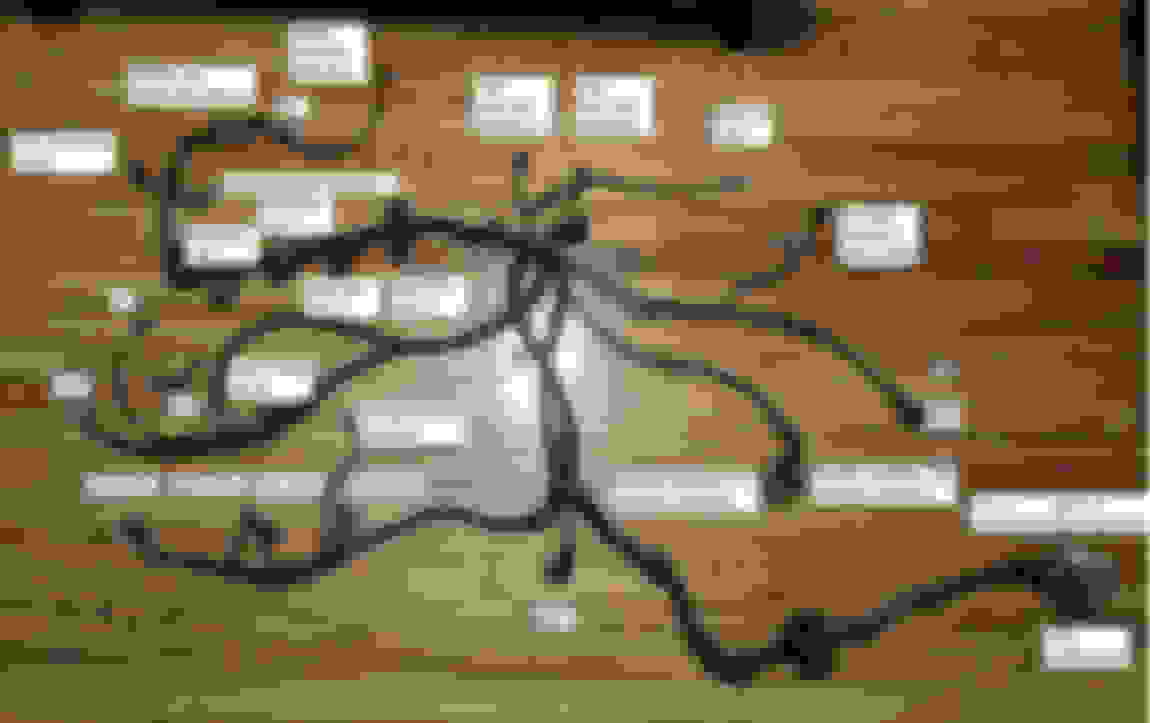
These are the updates needed for the Engine Wire Harness. Need to use an 02-04 RSX Type S Harness.
I used new pigtail connectors for the TPS, MAP, VSS, IAT, Back-Up Light, and AC Compressor Clutch
With the harness out of the car:
1. Swap Connector for TPS
a. RSX Connector -wire side
b. S2000 Connector – Wire side
c. Connect YEL/BLU VCC2 wire to position 3 on S2000 connector
d. Connect GRN/YEL SG2 wire to position 1 on S2000 connector
e. Connect middle wire to position 2 on S2000 connector
2. Swap Connector for MAP Sensor
a. RSX Connector – wire side
b. S2000 Connector – wire side
c. Connect YEL/RED VCC1 wire to position 1 on S2000 Connector
d. Connect GRN/WHT SG1 wire to position 2 on S2000 Connector
e. Connect GRN/RED MAP wire to position 3 on S2000 Connector
3. Swap Connector for Intake Air Temperature Sensor
a. RSX Connector – wire side
b. S2000 Connector -wire side
c. Connect GRN/YEL SG2 wire to position 1 on s2000 Connector
d. Connect RED/YEL IAT wire to position 2 on S2000 Connector
4. Swap VSS connector
a. RSX Connector OEM pin locations: 1 - BLK (ground), 2- BLK/YEL (power), 3 - WHT/GRN (signal)
b. S2000 Connector
i. 1 YEL/BLU (POWER)
ii. 2 BLU/WHT (SIGNAL)
iii. 3 BRN/YEL (GROUND)
c. Connect BLK Ground wire to position 3 on S2000 Connector
d. Connect BLK/YEL VCC2 wire to position 1 on S2000 Connector
e. Connect WHT/GRN LG2 wire to position 2 on S2000 Connector
5. Swap Back-Up Light connector
and connect to Back-Up Light switch on transmission (27 – RSX EWH)
a. RSX Diagram –
b. S2000 Diagram –
c. Connect GRN/WHT wire to position 1 on S2000 Connector
d. Connect YEL wire to position 2 on S2000 Connector
6. Run wire from A/C Compressor Clutch connector along harness and through firewall grommet so that it ends near ECU Connector Plugs. Crimp K ECU pin on the end. This will be pinned into the E Connector in wiring part 2.
Final Product all wrapped up. (Not pictured AC Compressor Clutch Connector, I routed mine in the same direction as the IACV but at least 12" longer)
I recommend leaving it unwrapped until your connections are confirmed.
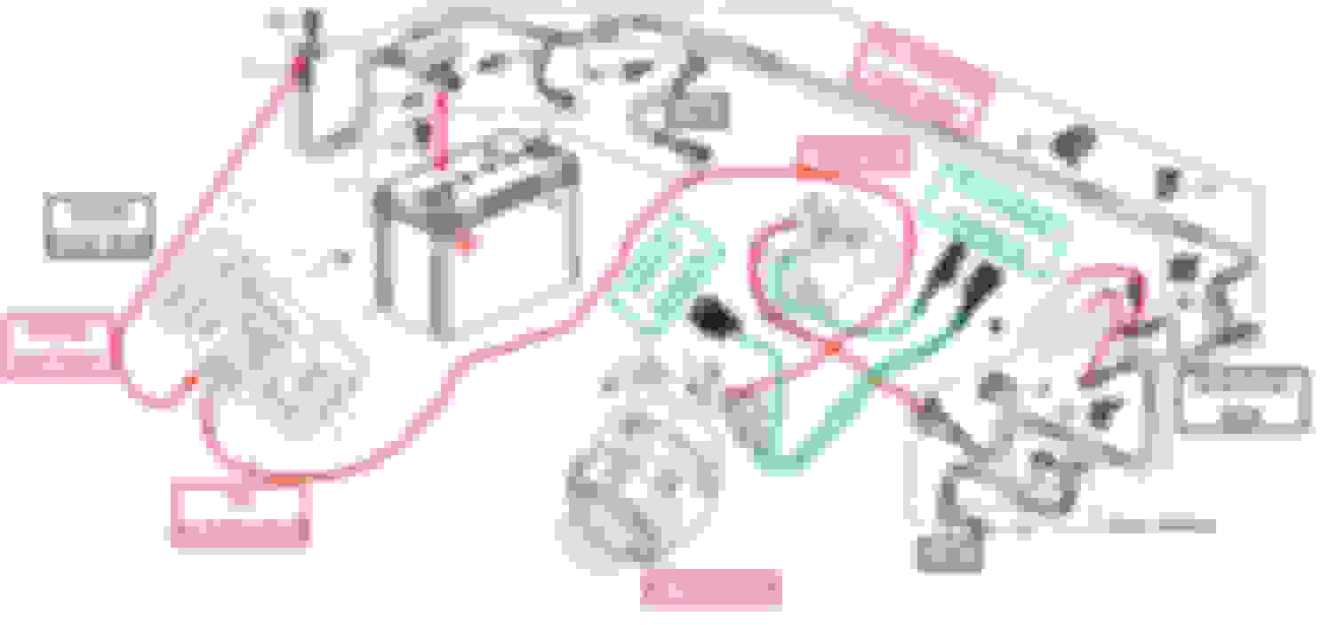
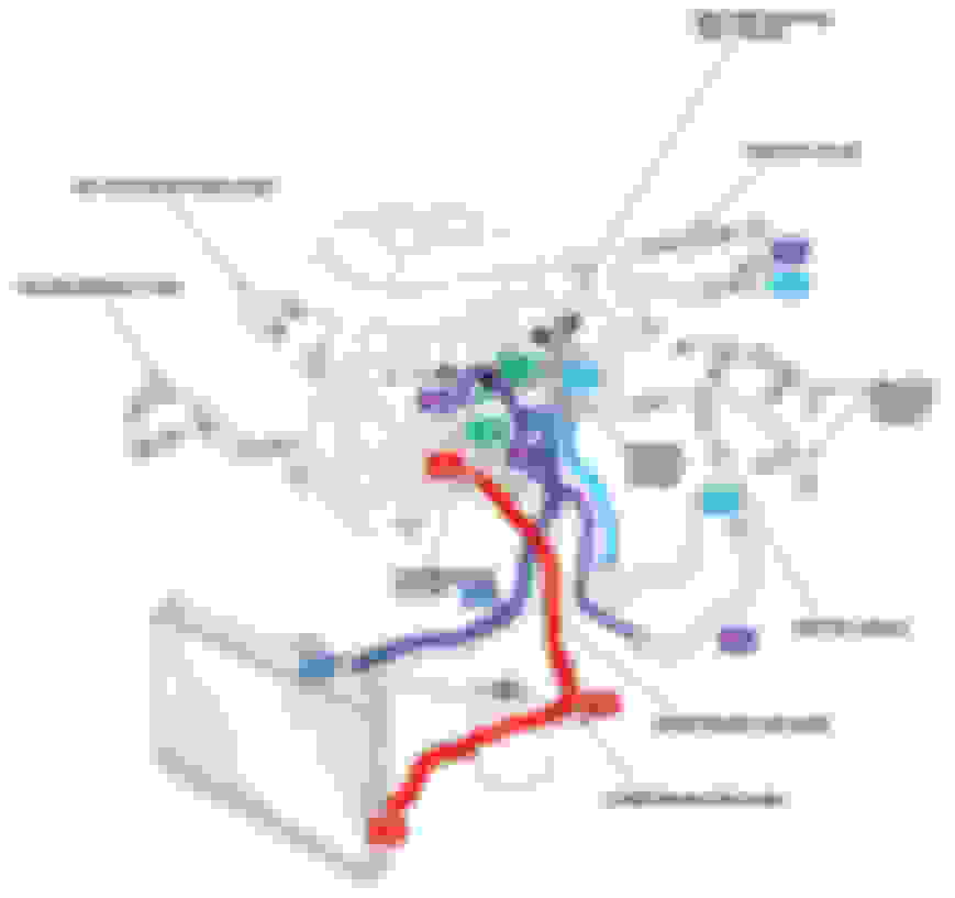
With your wiring harness ready to be put in, we move onto the charge harness. We will keep both battery connections (+ & -) from the S2000. We will need to run cabling from the fuse box to the alternator and connectors from the alternator, starter, and knock sensors to the wiring harness connectors.
S2000 Power Cable – (Should still be in car)
RSX Charge Harness Modified
Full Diagram
Make all these connections per the full diagram and then we get to move onto Cooling.
The cooling lines are annoying spaghetti, but I wanted to keep heat in my car. I was able to re-use the Radiator, Heater, and Thermostat Bypass Hoses. You will need to modify the Thermostat Heater Pipe, use a new o-ring, to connect to the Heater Hose. I cut mine before the second bend and routed it out of the K-Tuned swivel thermostat towards driver side strut tower to make the connection at the heater hose. I recommend unbolting the water outlet cover from the intake manifold and making the connections beforehand and then bolting the cover to the manifold (2 bolts), when it is installed (new o-ring). Make sure your hose clamps are tight to prevent any impossible to get to leaks.
Here is the legend for the cooling diagram:
Note: Coolant flows from A to C, etc.
Note: Disregard #7 if you have capped off your IACV and Throttle Body
I capped off my IACV and Throttle Body, but if you’d like to have that functional, this is how I would route it.
After you have made all your connections, I recommend jacking the front of your car up and filling your radiator with coolant to check for leaks. You can bleed the system after it is all put to together.

 04-10-2020, 10:44 AM